Posted on 1 Comment

Carbide Tip Lathe Tools

Shall the axe boast over him who hews with it, or the saw magnify itself against him who wields it? As if a rod should wield him who lifts it, or as if a staff should lift him who is not wood! – Isaiah 10:15

Back in May my folks picked up a lathe for my birthday and Christmas. My wife has expressed interest in turning so for Mother’s Day I picked up a pen turning kit with which she turned her first pen. One of the things she discovered was that turning the burl with the high speed steel lathe tools was… less than effective. So in the end I can’t give her a less than effective Mother’s Day gift so something must be done. We borrowed my father’s carbide lathe tool so she could finish up the pan and it worked great.

There are two major components to carbide tip lathe tools, the metal bar the carbide tip mounts into and a handle. I suppose you could get away with one, just using a bar, but that would seem like a shame since you are presumably making beautiful items with the tool on the lathe and making a nice looking handle really isn’t that much work.

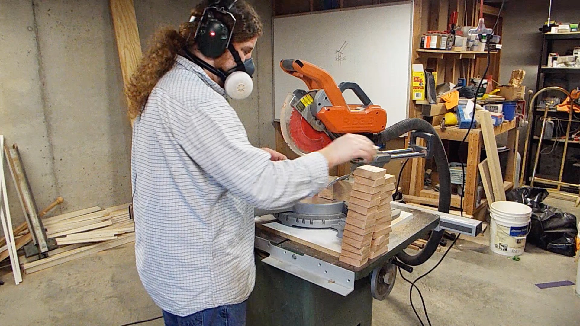
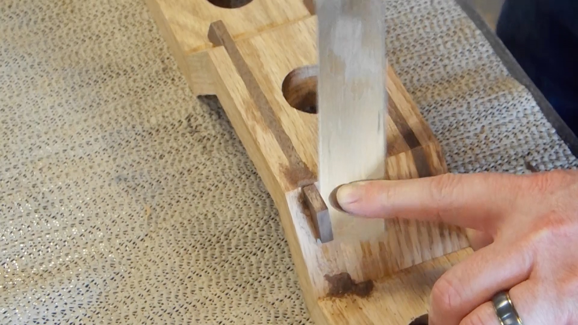
I used 1/2″ square and round steel bars. Each of the metal bars were cut down to about 12″ in length. At the bench grinder I ground away a rabbet about the thickness of one of the carbide cutters about 3/4″ down the length of the bar. Then using a file I cleaned up the rabbet to make a flat mounting surface. The bar was then mounted in a vice at the drill press to have a hole drilled to tap for a machine screw to mount the cutter. The machine screws needed a small amount of counter sinking so the hole was followed up with a wider drill bit just below the surface of the rabbet.

Tapping the hole is a bit of an art form. As you screw the tap into the hole small bits of the metal come off the walls of the hole which gum up the gullets of the tap. So you can only take a couple turns before the tap will just break off if you don’t reverse the cutting and clean out the gullets. A little machine oil helps keep things going mostly smoothly. Each hole took several minutes to tap since it took 5-8 times of screwing the tap in and reversing it to clear out the gullets. Testing each of the holes after tapping was also necessary to make sure that the threads engaged correctly.

After the holes were tapped the nose of the tool then needed to be ground back. Back at the bench grinder the tip is rounded so that then cutters will engage the wood without having the material on the lathe hitting the nose of the tool. Also, for smaller cutters it was necessary to grind back nearly all the way to the counter sink. But make sure you leave a complete flat surface for the cutter to rest on when tightened into the tool.

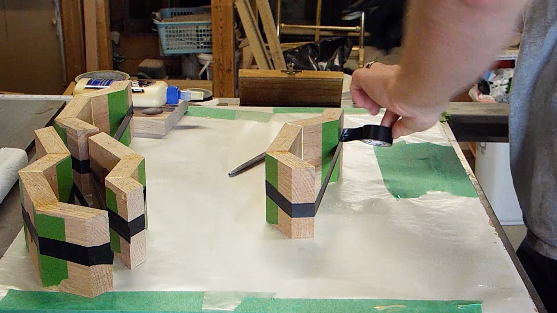
I rummaged through the scrap bin for small pieces which could be machined down to 3/4″ and about 12″ long. Then I matched the pieces I had remaining into groups of 2 matching pairs. Each pair was glued up to make a 1 1/2″ x 3/4″ half of a blank. Then each of the halves was hand planed flat so that it would join smoothly with the other half of the blank.

At the router table a dado was just slightly oversized into both halves of the blank about 4″ long. When the two faces were then placed against each other a bar could slide into the square hole and the bar was snug. The two halves were then glued together using a bar slid into the hole for alignment. Then removed once the clamps were applied.

Once the glue was dried a 1/2″ plug was created and cut flush with the end of the blank. This plug would be used on the tail stock side of the lathe to center the handle. The handled was then turned round at about 700 rpm. Once round the lathe was turned up to about 1500 rpm. By the tail stock a tenon for the ferrule was cut about 3/4″ long. Then the rest of the handle was shaped. Most of the handles wound up with a bulb on the end and another bulb around the ferrule. The last one was shaped with a slight taper from the back to front for about 2/3 the length and then widened slightly for the last bit up to the ferrule, which is a preferred shape in my hands.

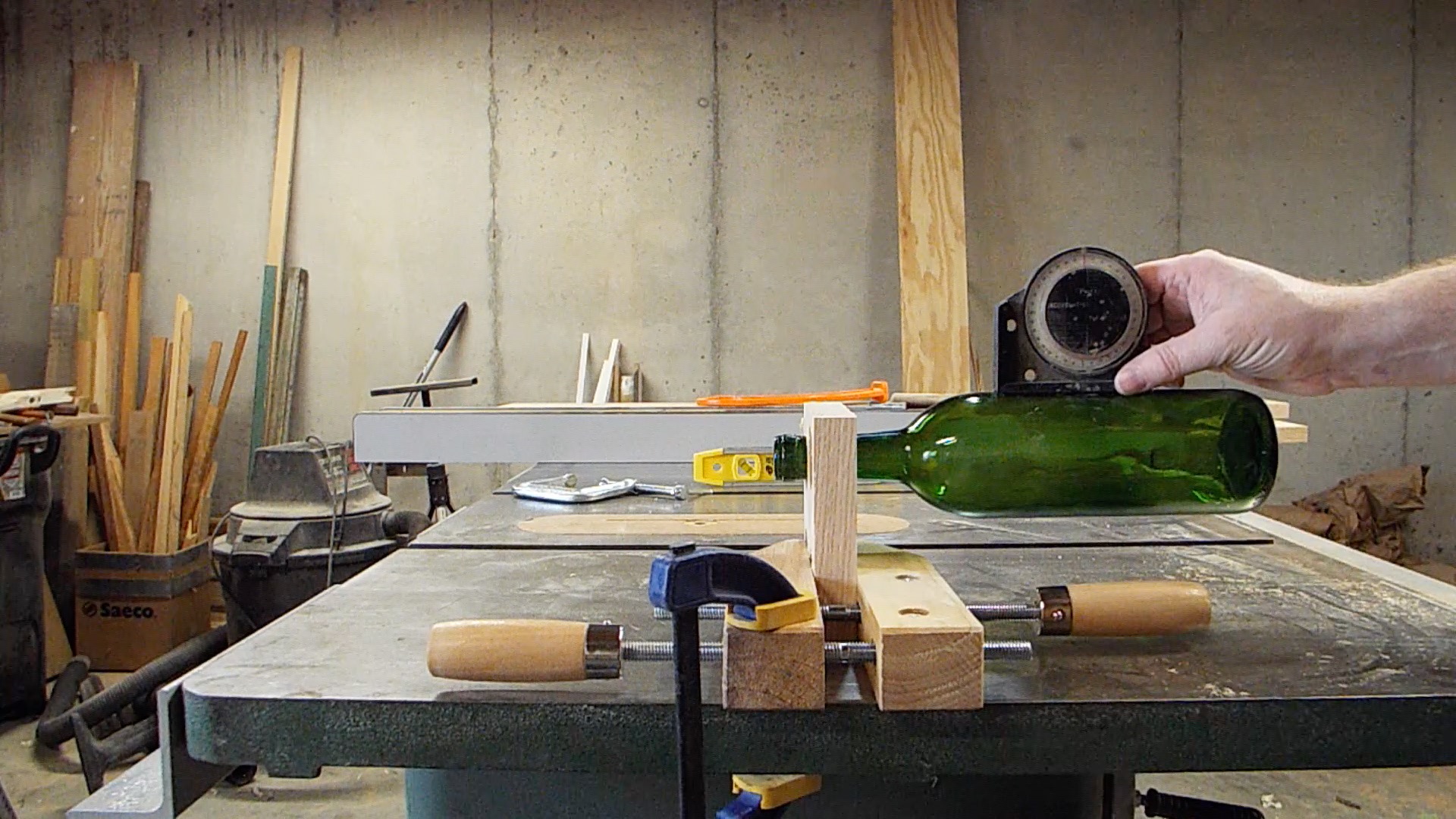
I had a couple 3/4″ copper pipe fittings which I cut in half on the lathe. I turned a quick 3/4″ dowel and used one of the carbide cutters to cut the fitting in half. At least that was the cleanest method I came up with without having a pipe cutter to use.

Assembly was done with epoxy. The epoxy was mixed and a little spatulaed down the hole in the handle. The bar was scored a couple times with a file and epoxy smeared on it and the bar was slid into the hole. Finally a little bit of epoxy was applied to the wood on the ferrule and the copper ferrule slid into place. The whole assembly was then clamped together and left to cure.

Due to the excessive amounts of epoxy all over the place I had to use an old chisel to scrap it off the bars. Then I used a file to file the epoxy off of the ferrule, which was good, since they looked much better after being evenly filed. And the handles themselves were re-sanded to 600 grit because of the epoxy all over those. Finally boiled linseed oil was used to finish the handles and they were hung up and left to dry.

Posted on 1 Comment

Settlers of Catan

So, whether you eat or drink, or whatever you do, do all to the glory of God. – 1 Corinthians 10:31

Summers Woodworking hosted the 3rd Annual 2×4 Challenge Contest this year, which is basically a challenge to make something out of an 8′ framing 2×4. A number of youtube woodworkers enter the challenge by creatively designing and creating an interesting project with that limitation and each year so far the entries have been impressive. This is the first year I’ve entered, hopefully with an entertaining and fun build for people to enjoy.

In college a friend introduced me to the game Settlers of Catan. It was one of the first euro-style games that became pretty popular in the US and for good reason. It is very well balanced and a style of game which keeps all players engaged from start to finish. My friend and I are competitive to say the least, cut throat and back-stabby might be a better description. My girlfriend at the time (and now wife) at the time often was often manipulated into turning the tide in games where it was coming down to either him or I winning, so she really got tired of playing and since I haven’t played the much at all. But out of respect for the game, I thought it might be fun to enter the 2×4 challenge with a build of the game.

I will cover the hardest technical hurdle to pull off this build: making a satisfactory card for all of the resource cards in the game. I’ve seen others try different ideas, but mostly those involved re-sawing on a bandsaw and winding up with a fairly rigid card. My goal was something closer to a playing card. During April I prototyped the idea with some shavings from the Puzzle Picture Frame panel glue up and eventually moved to pine 2×4.

The first issue that had to be addressed was material. I started with some .001″ shavings of maple. The shavings themselves were curled and ripply, so I used an iron to smooth them out. This worked acceptably well for the most part, but the really thin shavings just did not hold flat very well and the ripple would return with humidity. I adjusted the plane to .005″ and took some shavings off of some scrap 2×4 in the shop. These would start to shatter as I uncurled them which was a show stopper. I then came up with the idea of dampening the wood before ironing it. This worked great as the wood would absorb the water and soften up and allow me to uncurl it before pressing it with an iron. Issue #1 solved.

The shavings themselves were not sufficiently stable to use for cards and could break or chip easily. Laminating up the now ironed shavings was the next tricky aspect to address.

I thinned out some wood glue and brushed it on to each side of a shaving and offset the joints to make a 2 layer sheet of shavings. I spread this sheet out between a top and bottom layer of wax paper and pressed it between two sheets of glass. The glass itself was about 5/8″ thick and over a foot wide and even longer. Not sure how long the setup should cure, I left it for two days. After two days the shavings were still damp and the glue had not cured. I took the top layer of wax paper off to allow it air to dry. Once it was dry the shavings were as stuck to the wax paper as they were themselves. Not going to work.

Another iteration was attempted with a heavy cut of shellac. This also proved a failure when pressed between the sheets of glass as the shellac would not cure. When removing the weight of glass and the top sheet of wax paper the sheet of shaving did cure. However without being pressed together the shavings curled at the edges and did not bind between the upper and lower strips. All I got out of it were some shavings with shellac. This was attempted again with lacquer with similar results. Lesson: finishes are not glue.

A final attempt before looking at an epoxy, I stumbled upon contact cement. Interestingly you need to provide your birthday when purchasing contact cement. I’ve not been carded more for buying contact cement than alcohol. A thin film of contact cement was applied to a single side of a shaving. Then each shaving was lined up next to each other with a slight overlap. A top layer was then laid out on top of the previous with a thin layer of contact cement. Then the wax paper and glass treatment. I left it to cure overnight and in the morning we had success. The edges of the sheet was frayed, but the over all integrity of the sheets were sufficient for card stock. Due to the overlapping at the seems a quick sanding knocked those down into a serviceable surface to be able to do laser toner transfers.

Much of the rest of the project was fairly straight forward to accomplish and is covered in the video. A fair bit of it is just standard woodworking with a the usual challenges. The dyeing of the components is something featured in the Puzzle Piece Frames video with a slight variation. And the making of the dice is covered also in this video with the making of the pips perhaps one of the most fun parts of the build.

Music Links
http://freemusicarchive.org/music/josh_woodward/

Posted on Leave a comment

Wine Racks

You have put more joy in my heart than they have when their grain and wine abound. – Psalms 4:7.

This last Christmas my folks picked up a wine kit for my wife. Right after the New Year she started a pinot noir blueberry. Last month she wound up with 29 bottles! It seemed like it would be a good idea to make some wine racks to give her a way to display her wine.

I started by going through the stack of wood in the machine room looking for some pieces I could get some clear sections out. I used the miter saw to cut out the knots. Those pieces were then face jointed and then planed to about 3/4″ thickness. Then a single edge was jointed so I had a good edge to run on the table saw for ripping to width. I ripped the main piece about a half inch wider than the bottles Elizabeth had used for her wine.

Stacked Components
Components for the Wine Racks stacked next to the miter saw.

The wine rack is composed of 3 basic components, a wide trapezoid which would have the hole for the bottles, parallelogram pieces which would offset the bottle holders, and then smaller trapezoids which would be the tip and bottom of the rack. On the miter saw I set the angle to 22.5º. A stop block was setup for the for each of the cuts. I did all the cuts for each of the pieces batched together and would reset the block for the next piece.

I did some research and the only consensus I could find was that the cork needed to be wet. Some folks suggested a 5º incline was necessary for optimal and other that minimizing the surface area to reduce oxidization. Though I think most of that is some wine snobbery poking through in the guise of science. I figured a horizontal orientation was going to be sufficient.

Bottle Horizontal
The bottle is horizontal after the hole has been drilled at 16º.

I then had to figure out the logistics of holding the wine bottle. A little trial and error found that a 16º was required to get the bottle level with the properly sized hole. This was done by finding that the bottle was roughly off by that amount when I drilled the hole at 90º. To verify this I used a temporary jig to drill at 16º. When that checked out I made a permanent jig which mated with the same 22.5º angle which the cuts would wind up being at. I was able to batch off each of the bottle holders at the drill press.

Glue Up with Tape
Glue up using the miter tape technique and electric tape as the clamping pressure.

I used the tape technique which is used to glue up miters, putting tape on the outside of the joint and adding glue. Then the joint is pulled together, which I used some electrical tape. The tape had enough stretch to it to provide enough clamping power. Though the glue up was slow going since I had to only do a single joint at a time, since each joint pulled the opposite direction.

Since all the joints were effectively butt joints I figured splines were necessary to reinforce the joints. I ripped some walnut down to about a 1/4″ for material to use as splines. I then took a measurement off the spline material and setup the dado stack to be just shy of that measurement. This allowed me to finesse the splines to exactly the right size on the belt sander. Glue was applied inside the dados and the splines were slid in. Using cauls each spline was clamped.

Splines
The splines having their ends removed after being planed flat.
Once the glue was dry I used a block plane to bring the splines flush with the rest of the rack. A flush cut saw was used to trim the ends of the splines to the surface of the angled pieces of the rack. At that point the rest of this part of the rack was sanding. The palm sander was used for the most part, but a certain amount was necessary to do with hand sanding. I used the smallest drum from my drill press drum sander to cleanup the holes for the wine bottles.

The backs were a simple glue up of oak with a couple walnut slats. These were then face jointed and planed to thickness of about 3/8″. These were then squared up on both ends, about a 1/2″ larger in each dimension of the rack component. Then the ends were partially trimmed to the same angle as the top and bottom of the rack at 22.5º.

The racks were attached to the backs by pre-drilling the back and recess. These were clamped onto the rack and the rack itself was pre-drilled to keep it from splitting when the screws were attached. The 1/2″ forstner bit was missing so I used a 1/2″ brad tip bit to put a recess on the face which will get plugged by some 1/2″ walnut dowel once mounted on the wall.

Finally a finish of shellac was applied after wiping the whole thing down with a microfiber cloth to remove the dust. A few coats of shellac with some sanding before the last coat gives it a nice amber finish which looks good on oak and walnut. The completed project is shown below.

Wine Racks
Completed wine racks loaded up on the wall.

Music Links
http://freemusicarchive.org/music/Jahzzar/

Posted on Leave a comment

Recurve Bow

For not in my bow do I trust, nor can my sword save me. But you have saved us from our foes and have put to shame those who hate us. – Psalm 44:6-7

Dominic Bender on Youtube issued a challenge he called, “The Challenge Tree.” The basic premise is that the woodworker would grab some log or live edge piece of wood which was not taller than the participant and such that they could carry it, and then make something with it. As far as challenges go, it seemed pretty simple to keep within the guidelines and spirt of it.

The last couple years we’ve been leasing out some of our property to a local farmer. And on that land there is a small stand of poplar tree which we affectionally call the “Quarter Acre Wood” a la Winnie The Pooh. The farmer cleared a couple of the smaller trees around the stand digging them up and pushing them into the others. I found one that seemed like it would be large enough to get the material I needed from and cut it down and moved it to the basement to thaw for the night.

It took some doing, but with a reciprocating saw, duct tape, and a couple more or less dangerous cuts I managed to get the root bundle off the tree. The log was then cut in half into about 3′ sections. I processed both on the jointer to create two square and flat edges. With one I ripped thin slats for the limb lamination and the other I ripped another parallel edge for the stave of the bow.

The profile of the stave was drawn onto one of the sides and the face was drawn onto the back. Then I used the bandsaw to rough out the profile saving the off cuts as I went. The off cuts were then taped back onto the log and it was turned 90º to cut the face of the stave on the bandsaw. The next step was to use rasps and files to do the basic shaping. The handle and arrow support was where most of the work was done and everything was just rounded over some. I then sanded the rough marks with some high grit sand paper and worked up through to 220 grit sand paper.

To do bent lamination I needed a form. I cut some scrap plywood down to equal sizes which would hold the laminations. The plywood sheets were then laminated up with glue and clamps. I traced the shape of a limb on the form and brought it over to the bandsaw. When the form was cut I took two passes, one along the top line and the second cut along the bottom line. This allowed the form to handle the thicker bottom of the limb. I then sanded the insides of the form and taped some padding on each side of the form.

The slats for the limbs were pretty rough when they came off the bandsaw. I used a block plane to take out the highest spots and bring them close to flat. The jack plane was used to create a smooth taper of 3mm to 1mm along the length of the slat. I mixed the epoxy and applied it to both sides of the slats for 3 slats. Once sandwiched together I pressed them into the form with clamps and tightened them down with additional clamps. After two days the forms were released and I drew the shape of the limb and brought it over to the bandsaw. A couple quick cuts and I had the basic rough shape of the limb. Two were clamped together and a block plane was used to bring them both to the same shape. I then sanded the limbs remove any sharp edges and make them flex more evenly, so as to not twist.

I used a forstner bit to make a smooth spot for the flange nut, which would be used to secure the limbs on the stave. I had to then widen the first 3/8″ with another drill bit for the barrel of the flange nut. Next the hole was bored for the shaft of the of the bolt which would hole the limb. The final part of the operation was to duct tape the limb in place while drilling the holes through the limb.

I attached each limb separately one at a time. One issue became apparent with the flange nut and bolt I was using. The nut would keep spinning, despite the tightness around of the nut in the wood and I planned in the future I would epoxy that in place to keep it from spinning. However, when I was testing the limb for flex I found another fatal flaw. The limb just snapped beyond a point. Investigation found that it was along a knot in one of the plys in the limb. I used the last remaining slat that I had, which had originally been rejected, to attempt a replacement limb. The replacement limb suffered the same fate as the original.

Lessons learned: poplar is far too weak of a wood to use for bow limbs. Knots are incredibly weak compared to straight grain.

Links
Dominic Bender’s Challenge Tree Playlist

Music Links
http://freemusicarchive.org/music/Jahzzar/